Graphic Buffer, Multiple Ring Buffer Tools
Graphic Buffer
How to use Graphic Buffer Tool in ArcToolbox ArcMap ArcGIS??
 |
| Graphic Buffer Tool |
Graphic Buffer Table Tool, Proximity Toolset, Analysis Toolbox
Graphic Buffer
Creates buffer polygons
around input features to a specified distance. A number of cartographic shapes
are available for buffer ends (caps) and corners (joins) when the buffer is
generated around the feature.
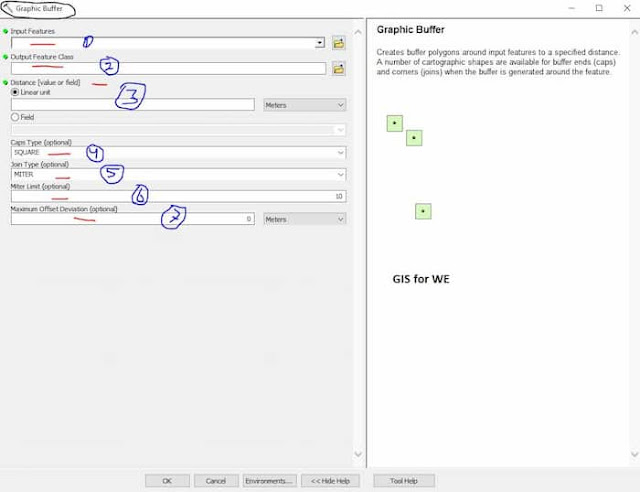
1. Input Features
The input point, line,
or polygon features to be buffered.
2. Output Feature Class
The feature class
containing the output buffers.
3. Distance [value or field]
The distance around the
input features that will be buffered. Distances can be provided as either a
value representing a linear distance or as a field from the input features that
contains the distance to buffer each feature.
If linear units are not
specified or are entered as Unknown, the linear unit of the input features'
spatial reference is used.
4. Caps Type (optional)
The caps (ends) of the input features that will be buffered. This parameter is only supported for point and polygon features.
- SQUARE—A square end around the end of a segment. This is the default.
- BUTT—End of the buffer of a segment would be perpendicular to the segment.
- ROUND—End of the buffer is round around the end of the segment.
5. Join Type (optional)
The shape of the buffer at corners where two segments join. This parameter is only supported for line and polygon features.
- MITER—Square or sharp shape around corners. For example, a square input polygon feature will have a square buffer feature. This is the default.
- BEVEL—Inner corners will be squared while the outer corner will be chopped off perpendicular to the furthest point of the corner.
- ROUND—Inner corners will be squared while the outer corner will be round.
6. Maximum Offset Deviation (optional)
The maximum distance the output buffer polygon
boundary will deviate from the true ideal buffer boundary. The true buffer
boundary is a curve and the output polygon boundary is a densified polyline.
With this parameter you can control how well the output polygon boundary
approximates the true buffer boundary.
If the parameter is not set, or is set to 0, the
tool will determine the maximum deviation for you. The default is strongly
recommended. Severe performance degradation, in the tool itself or in
subsequent analysis, could result from using a maximum offset deviation that is
too small.
See the Maximum Offset Deviation parameter
information contained in the Densify tool documentation for more details.
7. Miter Limit (optional)
Where line segments meet at a sharp angle and a
Join Type of MITER has been specified, this parameter can be used to control
how sharp corners in buffer output come to a point. In some cases, the outer
angle where two lines join is quite large when using the MITER Join Type. This
could.
Multiple Ring Buffer
How to use Multiple Ring Buffer Tool in ArcToolbox ArcMap ArcGIS??
 |
| Multiple Ring Buffer Tool |
Multiple Ring Buffer Tool, Proximity Toolset, Analysis Toolbox
Multiple Ring Buffer
Creates multiple buffers
at specified distances around the input features. These buffers can optionally
be merged and dissolved using the buffer distance values to create
non-overlapping buffers.
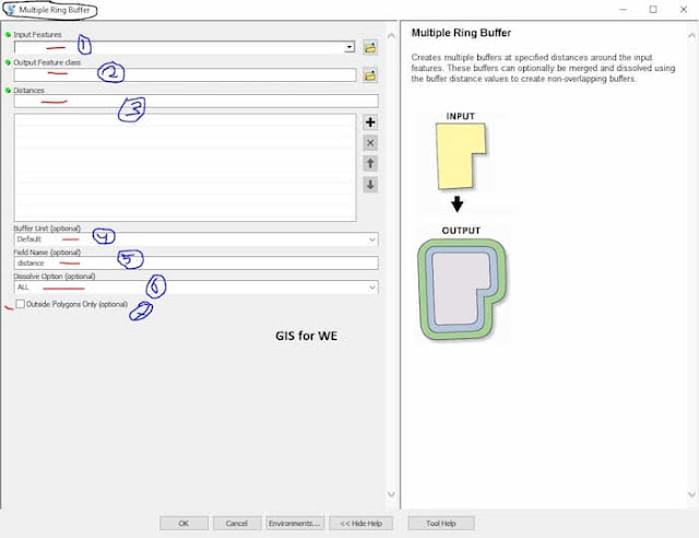
1. Input Features
The input point, line,
or polygon features to be buffered.
2. Output Feature class
The output feature class
that will contain multiple buffers.
3. Distances
The list of buffer
distances. Distances are entered individually and can be committed to the list
by pressing the Add button. The Distances list is managed using the side-panel
controls.
4. Buffer Unit (optional)
The linear unit to be
used with the Distance values. If the units are not specified, or entered as
'Default', the linear unit of the input features' spatial reference is used. If
the Buffer Unit is specified as 'Default' and the Output Coordinate System
geoprocessing environment has been set, its linear unit will be used.
5. Field Name (optional)
The name of the field in
the output feature class that stores the buffer distance used to create each
buffer feature. If no name is specified, the default field name is 'distance'.
This field will be of type Double.
6. Dissolve Option (optional)
Determines if buffers will be dissolved to resemble rings around the input features.
- ALL—Buffers will be rings around the input features that do not overlap (think of these as rings or donuts around the input features). The smallest buffer will cover the area of its input feature plus the buffer distance, and subsequent buffers will be rings around the smallest buffer which do not cover the area of the input feature or smaller buffers. All buffers of the same distance will be dissolved into a single feature. This is the default.
- NONE—All buffer areas will be maintained regardless of overlap. Each buffer will cover its input feature plus the area of any smaller buffers.
7. Outside Polygons Only (optional)
Determines if buffers will cover the input features. Valid only for polygon input features.
Unchecked—Buffers will overlap or cover the input features. This is the default.
Checked—Buffers will be rings around the input features, and will not overlap or cover the input features (the area inside the input polygon will be erased from the buffer).

Comments
Post a Comment