MultiPatch Footprint, ASCII 3D to Feature Class
MultiPatch Footprint
How to use MultiPatch Footprint Tool in Arc Toolbox ArcMap ArcGIS ??
 |
| MultiPatch Footprint |
MultiPatch Footprint Tool, From Feature Class Z to ASCII Toolset,
Conversion Toolset, 3D Analyst Toolbox
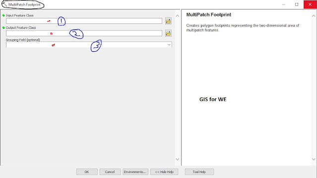
MultiPatch Footprint
Creates polygon
footprints representing the two-dimensional area of multipatch features.
1. Input Feature Class
The multipatch feature
whose footprint will be generated.
2. Output Feature Class
The resulting footprint
polygon feature class.
3. Grouping Field (optional)
The field used for
combining multipatch features so that they contribute to the same footprint
polygon.
ASCII 3D to Feature Class
How to use ASCII 3D to Feature Class Tool in Arc Toolbox ArcMap ArcGIS ??
 |
| ASCII 3D to Feature Class |
ASCII 3D to Feature Class Tool, From File Toolset, Conversion
Toolset, 3D Analyst Toolbox:
ASCII 3D to Feature Class
Imports 3D features from one or more ASCII files stored in XYZ, XYZI, or GENERATE formats into a new feature class.
1. Input
2. Input File Format
The format of the ASCII files that will be converted to a feature class.
·
XYZ—Text file that contain geometry information stored as XYZ
coordinates.
·
XYZI—Text files that contain XYZ coordinates alongside intensity
measurements.
·
GENERATE—Text files structured in the Generate format.
3. Output Feature Class
The feature class that will be produced by this
tool.
4. Output Feature Class Type
The geometry type of the output feature class.
·
MULTIPOINT—Multipoints are recommended the input data contains a
large number of points and attributes per feature are not required.
·
POINT—Each XYZ coordinate will produce one point feature.
·
POLYLINE—The output will contain polyline features.
·
POLYGON—The output will contain polygon features.
5. Z Factor (optional)
The factor by which z-values will be multiplied. This is typically used to convert Z linear units to match XY linear units. The default is 1, which leaves elevation values unchanged. This parameter is disabled if the spatial reference of the input surface has a Z datum with a specified linear unit.
6. Coordinate System (optional)
The coordinate system of the input data. The default is an Unknown Coordinate System. If specified, the output may or may not be projected into a different coordinate system. This depends the whether the geoprocessing environment has a coordinate system defined for the location of the target feature class.
7. Average Point Spacing (optional)
The average planimetric distance between points of the input. This parameter is only used when the output geometry is set to MULTIPOINT, and its function is to provide a means for grouping the points together. This value is used in conjunction with the points per shape limit to construct a virtual tile system used to group the points. The tile system's origin is based on the domain of the target feature class. Specify the spacing in the horizontal units of the target feature class.
8. File Suffix (optional)
The suffix of the files to import from an input folder. This parameter is required when a folder is specified as input.
9. Decimal Separator (optional)
The decimal character used in the text file to differentiate the integer of a number from its fractional part.
- DECIMAL_POINT—A point is used as the decimal character. This is the default.
- DECIMAL_COMMA—A comma is used as the decimal character.

Comments
Post a Comment