Detect Graphic Conflict, Propagate Displacement Tools
Detect Graphic Conflict
How to use Detect Graphic
Conflict Tool in ArcToolbox ArcMap ArcGIS??Detect Graphic Conflict Tool
Detect Graphic Conflict Tool, Graphic Conflicts Toolset, Cartography Toolbox
Detect Graphic Conflict
Creates polygons where
two or more symbolized features graphically conflict.
1. Input Layer
The input feature layer
containing symbolized features. CAD, coverage, or VPF annotation, dimensions,
charts, dot-density or proportional symbols, raster layers, network datasets,
or 3D symbols are not acceptable inputs.
2. Conflict Layer
The feature layer
containing symbolized features potentially in conflict with symbolized features
in the input layer.
3. Output Feature Class
The output feature class
to be created to store conflict polygons. It cannot be one of the feature
classes associated with the input layers.
4. Conflict Distance (optional)
Sets the conflict
distance. Temporary buffers one-half the size of the conflict distance value
are created around symbols in both the input and conflict layers. Conflict
polygons will be generated where these buffers overlap. Conflict distance is
measured in page units (Points, Inches, Millimeters, Centimeters). If you enter
a conflict distance in map units, it will be converted to page units using the
reference scale. The default conflict distance is 0, where no buffers are
created and only symbols that physically overlap one another are detected as
conflicts.
5. Line Connection Allowance (optional)
The radius of a circle, centered where lines join, within which graphic overlaps won't be detected. This parameter is only considered when the input layer and the conflict layer are identical. Zero allowance will detect a conflict at each line join (if end caps are overlapping). Line connection allowance is calculated in page units (Points, Inches, Millimeters, Centimeters). If you enter a conflict distance in map units, it will be converted to page units using the reference scale. The value cannot be negative; the default value is 1 Point.
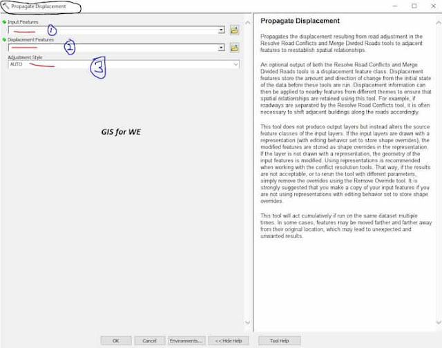
Propagate Displacement
How to use Propagate
Displacement Tool in ArcToolbox ArcMap ArcGIS??Propagate Displacement Tool
Propagate Displacement Tool, Graphic Conflicts Toolset, Cartography Toolbox
Propagate Displacement
Propagates the
displacement resulting from road adjustment in the Resolve Road Conflicts and
Merge Divided Roads tools to adjacent features to reestablish spatial
relationships.
An optional output of
both the Resolve Road Conflicts and Merge Divided Roads tools is a displacement
feature class. Displacement features store the amount and direction of change
from the initial state of the data before these tools are run. Displacement
information can then be applied to nearby features from different themes to ensure
that spatial relationships are retained using this tool. For example, if
roadways are separated by the Resolve Road Conflicts tool, it is often
necessary to shift adjacent buildings along the roads accordingly.
This tool does not
produce output layers but instead alters the source feature classes of the
input layers. If the input layers are drawn with a representation (with editing
behavior set to store shape overrides), the modified features are stored as
shape overrides in the representation. If the layer is not drawn with a
representation, the geometry of the input features is modified. Using
representations is recommended when working with the conflict resolution tools.
That way, if the results are not acceptable, or to rerun the tool with different
parameters, simply remove the overrides using the Remove Override tool. It is
strongly suggested that you make a copy of your input features if you are not
using representations with editing behavior set to store shape overrides.
This tool will act cumulatively
if run on the same dataset multiple times. In some cases, features may be moved
farther and farther away from their original location, which may lead to
unexpected and unwanted results.
1. Input Features
The input feature layer
containing features that may be in conflict. May be point, line, or polygon.
2. Displacement Features
The displacement polygon
features created by the Resolve Road Conflicts or the Merge Divided Roads tools
that contain the degree and direction of road displacement that took place.
These polygons dictate the amount of displacement that will be propagated to
the input features.
3. Adjustment Style
Defines the type of adjustment that will be used when displacing input features.
- AUTO—The tool will decide for each input feature whether a SOLID or an ELASTIC adjustment is most appropriate. In general, features with orthogonal shapes will have SOLID adjustment applied, while organically shaped features will have ELASTIC adjustment applied. This is the default.
- SOLID—The feature will be translated. All vertices will move the same distance and direction. Topological errors may be introduced. This option is most useful when input features have regular geometric shapes.
- ELASTIC—The vertices of the feature may be moved independently to best fit the feature to the road network. The shape of the feature may be modified slightly. Topological errors are less likely to be introduced. This option only applies to line and polygon input features. This option is most useful for organically shaped input features.


Comments
Post a Comment